2017/07/03

PyCharm 한번 써보자 with raspberry pi

라즈베리파이의 파이썬을 원격으로 사용해볼 목적으로 한번 사용해본다.


jetbrains에서 PyCharm으로 들어가면 프로페셔널 버전과 커뮤니티 버전을 사용할 수 있는데, 커뮤니티 버전은 무료로 쓸 수 있지만 remote interpreter 기능을 사용할 수 없다. 프로페셔널을 사용해야한다.

설치하고 실행시키면 이렇게 나온다.


Create New Project를 선택해보자.


Location에 원하는 위치를 설정하고, interpreter의 톱니바퀴를 클릭하면 Add Remote가 뜬다. 여기로 들어가자.


Host에 라즈베리파이의 IP address, User name에 pi, Password에 raspberry를 입력한다. 유저와 패스워드는 라즈베리의 디폴트값이므로 만약 다른걸로 변경했다면 그걸 입력해야한다.

Python interpreter path는 /usr/bin/python은 파이썬2다. 만일 파이썬3를 사용하려면 /usr/bin/python3을 입력하면 된다.

SSH를 사용한 PC와 라즈베리파이의 연결이므로 라즈베리의 SSH를 enable 시켜줘야 한다.


이제 프로젝트를  Create 해보자.


File -> New를 선택해서 파일을 하나 만들자. 난 hello_raspberry.py 파일을 만들었다.


이 파일을 라즈베리로 업로드하도록 설정해보자.
Tools -> Deployment -> Configuration으로 가보자.


왼쪽 상단의 녹색 + 를 클릭하자.


Name은 raspberry pi로 하고 Type은 SFTP로 정했다.
OK 하면 다음 화면이 뜬다.


SFPT host에 라즈베리의 IP를 입력하고 User name과 Password를 입력 후 Test SFTP connection을 클릭하면 설정에 문제없을 경우 Successfully connected to xxx.xxx.xxx.xxx 라고 팝업이 뜬다. 만일 그렇지 않을 경우 다시 설정을 확인해보자.

Mappings 탭으로 가면 로컬파일이 라즈베리의 어디에 저장될지 설정할 수 있다.


경로와 파일명까지 정확하게 적어줘야한다.

Deployment 설정이 끝났으니 이제 제대로 파일이 업로드 되는지 확인해보자.
Tools -> Deployment -> Upload to raspberry pi 를 선택하자.


파일 업로드는 문제없다.

Run으로 실행해봤는데...이게 제대로 실행된건지 알수가 없다. 라즈베리 화면엔 아무것도 안떠서...

GUI 간단한걸로 해보자.

from kivy.app import App
from kivy.uix.button import Button

class TestApp(App):
def build(self):
return Button(text='Hello World')

TestApp().run()


kivy 테스트 코드를 돌려볼련다.


Deployment의 mappings 설정을 hello.raspberry_kivy.py로 바꿔준 다음, 업로드 후 Run 해보자.


되네.


2017/07/01

L6470PD


Features
- operating voltage : 8 ~ 45V
- 7.0A out peak current(3.0A r.m.s.)
- Low Rds(on) Power MOSFETs
- Programmable speed profile and positioning
- Programmable power MOS slew rate
- Up to 1/128 microstepping
- Sensorless stall detection
- SPI interface
- Low quiescent and standby currents
- Programmable non-dissipative overcurrent protection on high and low-side
- Two-levels of overtemperature protection

Block diagram


약간 특이한 점이 있다면 모션 관련 커맨드가 내장되어 있다.
레지스터를 세팅하거나 읽어오는 커맨드도 있고, 그걸 사용하는거 외에 레지스터에 접근할 수 있는 방법은 없다.

STCK로 펄스를 입력해서 구동시키는 Step-clock mode를 사용하려고 해도 내부 레지스터 세팅을 바꿔줘야 하므로 SPI 인터페이스는 꼭 연결되어 있어야 한다.

SPI는 최대 5MHz로 구동되며 8비트 기반이다. 아래 다이어그램을 보는게 이해가 빠를터.


여러 바이트를 전송할 경우 각 바이트 사이에 CS 핀을 High로 올리고 적어도 tdisCS  (800ns)이상 유지시켜줘야 한다.


The L6470 controls the phase current applying a sinusoidal voltage to motor windings.
Phase current amplitude is not directly controlled but depends on phase voltage amplitude, load torque, motor electrical characteristics and rotation speed.

모터 스펙에 따라 아래 레지스터를 설정해야 할것이다.

KVAL_HOLD : 모터 정지상태의 KVAL
KVAL_RUN : 모터 정속 상태의 KVAL
KVAL_ACC : 모터 가속 상태의 KVAL
KVAL_DEC : 모터 감속 상태의 KVAL


Motor supply voltage compensation
The sinewave amplitude generated by the PWM modulators is directly propotional to the motor supply voltage(Vs). When the motor supply voltage is different from its nominal value, the motor phases are driven with an incorrect voltage. The L6470 device can compensate motor supply voltage variations in order to avoid this effect.

The motor supply voltage should be connected to the integrated ADC input through a resistor divider in order to obtain Vreg/2 voltage at the ADCIN pin when Vs is at its nominal value.


The ADC input is sampled at fs frequency, which is equal to PWM frequency.

Motor supply voltage compensation can be enabled setting high the EN_VSCOMP bit of the CONFIG register. If the EN_VSCOMP bit is low, the compensation is disabled and the internal analog-to-digital converter is at the user's disposal; sampling rate is always equal to PWM frequency.
어떻게 동작한다는건지 모르겠다...


STM32F103RCT6의 핀할당은 위 그림과 같다.

L6470을 두개 연결해놨다.
 
첫번째 L6470 인터페이스


두번째 L6470 인터페이스


MISO, MOSI, SCK 만 공통이고 나머지는 모두 따로 할당되어야 함.

SPI 설정은 아래와 같다


나머지 핀 설정은 아래와 같다.
            GPIO output level   GPIO mode          Maximum output speed  
SCS_1/2 :  High              Output Push Pull     Low
SR_1/2  :  High              Output Push Pull     Low
SW_1/2  :  High              Output Push Pull     Low 

           GPIO mode      GPIO Pull-up/Pull-down
BS_1/2    :  Input mode      No pull-up and no pull-down
FLAG_1/2 :  Input mode      No pull-up and no pull-down 

STCK는 일단 사용하지 않는다.


대충 세팅해서 함 돌려봤다.


2017/04/13

STM32 + Raspberry PI 보드를 만들어보자 -- 03. PCB Artwork

다 그렸다...


라즈베리파이로 공급하는 5V가 최대 2.5A 라길래 급히 5V/3A DCDC를 추가했다.


기존 설계파일과 같이 묶어서  v-cut으로 나눈 후 firstPCB에 발주보낼 예정이다.


firstpcb.com에서 견적을 내보니 $81.90이다. 배송비 포함하면 100달러 조금 넘을듯.


STM32 + Raspberry PI 보드를 만들어보자 -- 02. Schematic...

STM32CubeMX로 필요한 기능을 정리해봤다.


남는 핀은 40핀 헤더로 죄다 뽑아낼 예정이다.


활성화한 Peripheral을 순서대로 나열하자면

1. CAN1 Master Mode
2. I2C1
3. SDIO MMC 4 bits Wide bus
4. SPI1 Full-Duplex Master
5. SPI2 Full-Duplex Slave
6. SYS JTAG(5 pins)
7. USART2
8. USART3
9. USART6
10. USB_OTG_FS ORG/Dual_Role_Device

메인 기능은 일단 이걸로 하고 회로도 슬슬 그려보자.


24V, 5V, 3.3V 전원부부터


uart, usb, can, 485 등등 


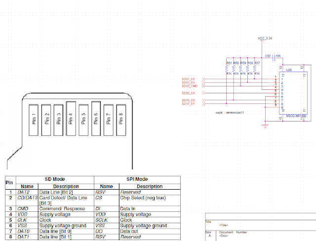
microSD


라즈베리파이 인터페이스용 40핀 헤더


MCU 파트


대충 그렸다.

자 다음... PCB


2017/04/12

STM32 + Raspberry PI 보드를 만들어보자 -- 01. OpenOCD로 stm32 프로그래밍하기

써먹을데가 좀 있을거같다.

처음 생각해본 컨셉은

1. 리눅스가 돌아가는 초저가 SBC를 메인 GUI로 사용하자.
2. Real Time 제어는 STM32에서 담당하자.
3. 라즈베리와 STM32 둘 사이의 통신은 UART or SPI
4. 라즈베리에서 다이렉트로 STM32의 플래시 프로그래밍이 가능했으면...

요정도로 시작한다.

라즈베리로 STM32를 프로그래밍 가능하도록 OpenOCD 기능을 먼저 테스트해보자.
adafruit의 문서를 참고했다.
여기서 사용하는 라즈베리는 Raspberry PI 3 model B 다.

1. sudo apt-get update


2. sudo apt-get install git autoconf libtool make pkg-config libusb-1.0-0 libusb-1.0-0-dev


3. git clone git://git.code.sf.net/p/openocd/code openocd-code


openocd-code 폴더가 보인다.

4. cd openocd-code
   ./bootstrap


5. ./configure --enable-sysfsgpio --enable-bcm2835gpio


6. make
   sudo make install


먼지 모르겠다만 여기까지 따라왔다. openOCD의 설정은 여기까지고 다음부턴 물리적인 연결이다.


별 어려운건 없다. GND, nRST, SWDIO, SWDCLK 요 4개의 핀만 연결하면 됨.


Adafruit의 설명은 at91samd 디바이스로 설명해놔서 STM32로 수정해서 진행한다.

openocd.cfg 파일을 만든다
=====================================================
source [find interface/raspberrypi2-native.cfg]
transport select swd

set CHIPNAME stm32f4
source [find target/stm32f4x.cfg]

# did not yet manage to make a working setup using srst
#reset_config srst_only
reset_config  srst_nogate

adapter_nsrst_delay 100
adapter_nsrst_assert_width 100

init
targets
reset halt

program hello_world_01.bin verify reset exit 0x08000000

reset
shutdown
=====================================================

내용은 === 제외하고 복붙 하면 된다.
내가 쓰는건 STM32F439이므로 다른걸 쓴다면 약간 변경해야 한다.

source [find target/stm32f4x.cfg] 이 부분은 해당하는 mcu의 cfg로 변경해줘야 한다.
/usr/local/share/openocd/scripts/tartget 에 cfg 파일들이 모여있으니 이 중 적당한걸 선택한다.


stm32를 쓴다면 stm32f0x.cfg, stm32f1x.cfg, stm32f2x.cfg, stm32f3x.cfg, stm32f4x.cfg, stm32f7x.cfg 파일만 쓰면 된다.

program hello_world_01.bin verify reset exit 0x08000000 이 부분은 업로드할 이미지 파일을 지정해 주는부분이다.

hello_world_00.bin 바이너리를 설정하고
sudo openocd로 실행하면


이런식으로 실행되고


흠...굳

hello_world_01.bin 바이너리를 설정하고
sudo openocd로 실행하면


실행은 화면은


라즈베리파이와 STM32를 4선으로 인터페이스해서 펌웨어 업그레이드는 가능해 보인다.

그럼 다음 단계로 넘어가자.